Introduction
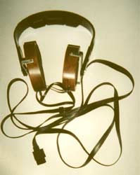
I undertook the construction of this headphone in 1995, a few years after my first ESL described elsewhere on this site. Due to the success of this (and some deceiving results with a "classical" ESL I had built), I decided to construct an electrostatic headphone based on the same principles: one stator and 2 diaphragm's.
The electrostatic headphone
At the time I begun the construction, I had gathered and read all possible books and articles I could find about electrostatic transducers, going from
F.V. Hunt's "Electrostatics", through P.J. Walker's "Wide Range Electrostatic
Loudspeakers", some articles in French, Dutch and German, to articles in
the English Magazine "Wireless World" and especially the article "P.D. Wilson, High quality Electrostatic Headphones" by J.P. Wilson in WW December 1968.
The interest of this article lies in the approach of J.P. Wilson, who was in fact most interested in the psycho-acoustic aspects involved in using headphones. This results in some constructional considerations, which I tried to take into account in my project. An electrostatic headphone should preferabily satisfy the following characteristics :
- The soundproducing area must be as large as possible. When this surface covers entirely the ear, then, the listener has a better spatial image for most reproduced frequencies. This eliminates the impression that sound is coming somewhere from inside the head, a phenomenon which is observed with most classical electrodynamic headphones.
- The distance between the diaphragm and the stator must be as small as possible to obtain a maximum soundpressure with signals (max. approximately 300 V rms) and polarisation voltages (600 to 1000V) which are significantly smaller then those found with normal electrostatic loudspeakers.
The electrostatic headphone element
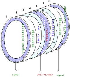
The electrostatic headphone element consists of a sandwich of 7 separate elliptical parts.
- A Signalelectrode consisting of an elliptical ring made out of single sided epoxyboard. A signal lead is soldered to the cupperside of the electrode. The cupperside is directed inside the element and pressed against the diaphragm (part 2).
- Diaphragm made of mylarsheet with Aluminium damped on one side.The metalized side is directed outwards and makes contact with the signal electrode (part 1). The not conducting side of the mylar film is glued to a plastic isolation ring (part 3).
- One mm thick plastic ring which isolates the diaphragm (part 2) from the stator (part 4).
- The stator is made of double sided epoxy print, with 3 mm holes drilled into it, to make it accousticaly transparent. The stator is glued at each side to a plastic isolation ring (parts 3 and 5). A small 0.8 mm hole is drilled through the stator and one end of the polarisation wire is pushed through this hole and soldered to the cupper at both sides of the stator.
- A 1mm plastic isdolation ring, glued at one side to the stator (part 4) and at the other side to the non metalized side of the second diaphragm (part 6).
- A second diaphragm consisting of mylar sheet metalized at one side. The non metalized side is glued to the plastic insulator ring (part 5), while the metalized side is pressed against the metalized side of the second signal electrode (part 7).
- A Second signal electrode consisting of an elliptical ring made out of single sided epoxyboard. A signal lead is soldered to the cupperside of the electrode. The cupperside is directed inside the element and pressed against the second diaphragm (part 6).
Description of the individual parts
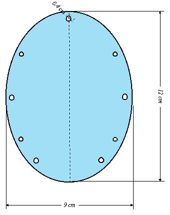
1. Stator
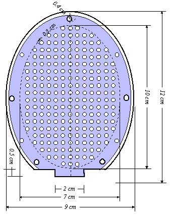
The stator of the prototype is elliptical (12cm x 9cm) and is made off
doublesided printplate (1,3mm thick). Holes with a diameter of 3mm were
drilled inside an inner ellips of 10cm x 7cm. They form an acoustical
grid which corresponds to the active sound reproduction area of the
element. The few holes outside the inner ellips serve to hold all
elements assembled with nylon bolts. Four of these bolts have a diameter
of 4mm, the other ones are 3mm bolts. At the underside of the ellips
some material has been cut, in order to let place for the
wireconnections and to facilitate the access to those connections. To
prevent arcing with the diaphragm, 2mm of cupper has been etched at the
outmost border of the outer ellips. The two cuppersides are
interconnected to obtain equipotential surfaces. The best place to make
this interconnection is at the lower part of the ellips in the 2cm wide
tab, where a 0,8mm hole can be drilled with some wire soldered at both
sides.The polarisationwire can then be soldered at one of the sides of
the same tab.
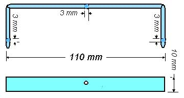
2. The Spacers
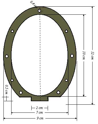
The isolation between the stator and diaphragm is made of a 1cm wide,
1mm thick elliptic ring, made of plastic material. Such a ring, is glued
at both sides of the stator. Holes, through which bolts can be attached
to hold supplemental parts, which will be added to hold the diaphragm
surface at some safe distance from the ear.
3. The Diaphragm
The diaphragm's are made of 6 µm mylarfilm with a thin layer of aluminium coating (damped) at one side. A piece of film, approximately 30cm by 30cm, with the conducting side nearwards, is disposed on a flat surface and stretched as much as possible, by applicating tape all over it's circumference. When the film is stretched, and no more ripples are present, one of the isolation pieces who is already glued to the stator is covered with some thin layer of glue and is disposed on the stretched film. To maintain as much pressure as possible, some weights (e.g. books) are placed on the other side of the stator. When the glue is dry (after 24 hours), the exessive film is cut away and the whole procedure is repeated at the other side of the stator. When the second diaphragm is ready a hair dryer is used to eliminate eventual residual ripples. This is done by moving the hair dryer at some distance (+- 10cm) of the surfaces of the diaphragm's.
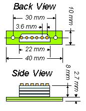
4. The signal connectors
The signal connectors are made of single sided printplate. Again some
parts are cut away at the underside of the ellips. The signalleads are
soldered outside the 2cm tab area present on the stator. The two
connector rings are identical, but, as the cupper side faces the
diaphragm, the part that is cut away is at the left for the back
electrode, and, at the right for the front electrode. In this way, the
polarisation lead is in the middle of the ellips, while the signal leads
will be at opposite sides, and well separated of each other.
Supplementary Parts
We now have some electrostatic elements, but it is of course not possible to place the diaphragm's directly to the ear! So, I have made some supplementary parts to arrive at a safe and comfortable headphone assembly. The first part is a bakelite elliptic ring, 4mm thick, one of which is placed at each side of the glued stator-diaphragm assembly. This means there is at least 5,3mm (because of the 1,3mm thick electrode) between the diaphragm and the outer flat surface of the bakelite ring. Those rings together with the grid described below will be attached to the electrostatic element with nylon nuts and bolds.To complete the assembly, I cut out ellipses of deployed black metal grid, a material used as protection against glowing embers, but that is also utilised to finish loudspeaker enclosures. Such a grid is placed at each side of the element, and now all constituting parts are fixed together by nylon nuts and bolts, that are put through the 9 holes which where drilled for that purpose through the different constuting elements.
Finally, some 5mm thick black foam ellipses, some 2 or 3 mm's larger then the 9cm x 12 cm ellipses are cut out, and will be fitted against the front and back protection grids, when the whole assembly is put into the wooden shell described below. The result is a totally protected element some 13,9mm thick, which is placed in a wooden shell :
Construction hints
All parts where hand made with saw, electril drill, knife, files and
sandpaper as only equipment. First ellipses of 12cm by 9cm, and 10cm by
7cm were drawn on cardboard and cut out. Those ellipses served to mark
the circonferences on the different materials. Next, an ellips of 12cm
by 9cm was sawn out of an aluminium sheet 5mm thick. This ellips was
finished with file and sandpaper to obtain a guide for the other
materials. Some holes, corresponding to the final fixing holes of the
electrostatic element where drawn : The different ellipses (bakelite,
printboard, plastic sheet, grid) where cut out or sawn to a dimension
slightly greater then the final ellips. With the aluminium ellips as a
guide, holes where drilled separately through all constituting pieces.
Then, the parts were assembled against the guide, in the order they
finally would be in the electrostatic element, and fixed together with
metalic nuts and bolts. The assembly was fixed and filed down to the
wanted dimension, using the aluminium piece as aguide. To cut out the
inner ellipses in the printboards and bakelite, I first marked the inner
circumference and draw 3 mm holes all along the circumference of the
inner ellips.
Final Assembly
The head assembly of an old electrodynamic headphone was recuperated and
some U-shaped pieces were made out of 3mm thick aluminium sheet, to fix
the electrostatic elements to this assembly :
I contacted Sennheiser, and could obtain the same low capacitance OFC
cable high voltage proof they use with their HE60 electrostatic
headphone. In order to connect this cable to an amplifier, I had still
to make some female connector, corresponding with the cable plug. I made
this with some resting pieces of cupperless printboard and plastic
isolator sheets (2mm thick), that I glued together, filed to the exact
dimensions and drilled 2,2mm holes in it, to hold 6 x 2mm thick bras
tubes as depicted in next figure :
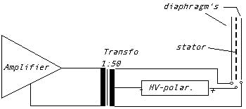
Amplifiers for electrostatic headphones
The headphones can be coupled to classical 10W-100W amplifiers by means of a special transfo, and by applying some 500-1000V polarisation Voltage :
A second way (described in WW november 1971), that can be used with tube amplifiers is shown below :
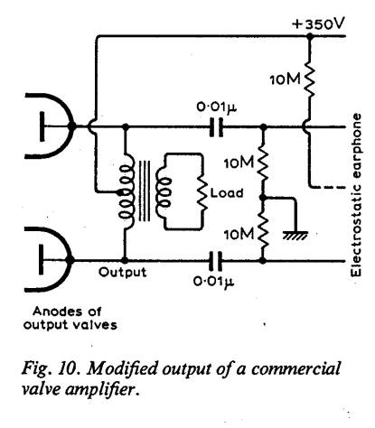
A third method consists in making a special headphone amplifier with tubes, transistors, mosfets or a combination of those elements. As the polarisation voltage is somewhere between 600 and 1000V and the signals are limited to maximum 350V rms, this is the ideal solution for electrostatic headphones.
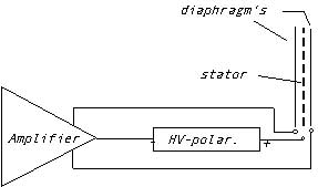
I have constructed several amplifiers of this kind, one of them which I will describe in another project on this site, was made especially for the headphones here described.