Introduction
My interest in electrostatic loudspeakers goes back to the early 70's, when I heard for the first time, during an HiFi-meeting, the famous QUAD electrostatics. As I didn't know at that time where to find the necessary materials, especially Mylar sheets to construct diaphragm's, I started the construction of a pair of closed boxes (85 cm high, 60 cm width, 40 cm deep), each equipped with 2 exotic Jordan Watts loudspeakers. The reason for this choice was, that the Jordan Watts was aimed to approach closely the characteristics of electrostatic speakers, due to the special construction of it's metallic cone.
In the beginning of the 90's, I was happy to detect an article by E.A.L.
Fikier in "HIFI-Luidsprekers 6", a special edition of the Dutch
magazine "Elektuur",about the construction of electrostatic
loudspeakers. Most of all, addresses (1) where mentioned, where I could
find Mylar sheets. My first idea was to make exactly the same
loudspeaker as that published by "Elektor". So, I ordered the necessary
materials, and prepared myself to start the construction. But, when my
wife saw the packet of steel plates, she asked me what I was going to do
with that. When I told her, I was going to construct a pair of full
range electrostatic loudspeakers, 240cm high and 67cm width, to replace
the above mentioned boxes in HER living room, I got a categoric NO.
Luckily, the existing boxes where already big, so, when I promised her, I
would reduce the size of the planned speakers to something nearly of
the same dimensions, peace was restored.
This was the starting point of a new approach, that led to an ESL with central stator and external diaphragm's. For the end of the history, I can tell you, that the the speakers whose construction is described below found finally their place in HER living room, and, for almost 10 years now, SHE enjoys daily the result. My experience with electrostatic speakers didn't stop there, and, I also constructed several electrostatic headphones, but that's another story. Many of the techniques that I used to build my first ESL's where described in the article of Mr. Fikier, who also wrote an excellent book : "Elektrostatische luidsprekers. Zelf bouwen of zelf kopen" ISBN 90-5381-029-3, book that I can recommend you, if you understand Dutch
Working Principles
The movement of the diaphragm in an electrostatic loudspeaker is caused by the electrostatic forces that act on it. There exist symmetrical and asymmetrical constructions. With asymmetrical constructions (fig 1.a) only limited diaphragm movements are allowed and distortion is worse then with symmetrical constructions. The symmetrical assemblies can be divided into two types :
- One moveable diaphragm is placed between two fixed perforated electrodes (fig 1.b) that are transparent for the sound. When the electrical charge on the diaphragm is held constant, then this type of speaker will still perform linearly with relatively important diaphragm movements. The electrostatic loudspeakers (QUAD,..) and electrostatic headphones (Stax, Sennheiser,..) that can be found today are of this type.
- One fixed perforated electrode, which is transparent for the sound, and, surrounded on both sides by a moveable diaphragm. The two diaphragm's are acoustically coupled by the gas(normally air) between them (fig 1.c). The force excerced on a moving diaphragm is a function of the distance between that diaphragm and the fixed electrode, but, as an increment of the distance of one diaphragm corresponds to a decrement of the distance of the other diaphragm there exist some distortion forces with opposite directions that eliminate each other partly because of the acoustic coupling, and so, this type is also quite linear for greater diaphragm movements.
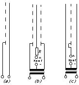
Figure 1, Schematic construction of electrostatic loudspeakers
The diaphragm
The deviations of the diaphragm are limited by the distance to the fixed electrodes. So, a large diaphragm surface is necessary to obtain a sufficiently high acoustic output power at low frequencies. This is the opposite of what happens with dynamic loudspeakers, where a small surface and large deviations are common.
The first solution is acoustically better, because a large diaphragm is coupled more tightly to the air. An enclosure, with it's inherent disadvantages (added self resonances), is not necessary, FM-distortions are minimal and impulse reproduction is excellent, because of the high damping of the entire diaphragm surface by the air.
The diaphragm of an electrostatic loudspeaker must be as light as possible, but, it may not be mechanically distorted during it's use. Today this combination of characteristics is easy to obtain with plastic materials. For electrostatics with 2 stators ( fig 1.b) it is important that the electric charge is constant over the whole diaphragm surface, that's the reason why the diaphragm sheet is mostly coated with a thin layer of material with high resistivity characteristics (> 1010 O/cm). An interesting article about coating The Original Quad Diaphragm Coating. A Direct Replacement" has been written by Gary Jacobson.
Electrostatics with a central stator (fig 1.c) don't work suiting the constant charge principle, so, another kind of diaphragm e.g. a plastic film with some metal damped on it (e.g. Aluminum)can be used instead
Until a certain frequency, which in practical situations is in the middle of the covered frequency range, the diaphragm motion is determined by the moving air mass, so, that the system in this frequency range is damped by the mass. Above this frequency the acoustical resistance is constant, and, at the same time the acoustic power.
With round shaped diaphragms some difference is noted at the limit of the two frequency ranges.. Because the acoustical resistance is determined by the surface and the vibrating air mass at the shortest wide of the diaphragm, it is possible to eliminate this difference in output power, by using a diaphragm that is strip-shaped. A benefit for this kind of construction is, that the radiation angle for high frequencies is greater. This principle can be used in practical designs, by dividing the total width of the speaker in several strips of varying width.
The fixed electrode(s)
The fixed electrode(s) must be transparent for sound and may not have some tendency to self resonation Practically different constructions are possible : perforated metal sheets, isolated wires, etc.. The metal of the fixed electrodes must be isolated as well as possible to prevent arcing due to high polarization voltage (e.g.Uretan painting ).
Polarization
The amplitude of the alternating audio signal applied to the fixed electrodes (fig 1.b) or the diaphragms (fig 1.c) must be low compared to the polarization voltage Vpol. As the sensitivity and efficiency increase with the charge Q on the diaphragm, Q and Vpol (because Q=C.Vpol) must be as high as allowed. The maximum charge is determined by the distances between the electrodes; depending on the construction, polarization voltages between 800V and more can be observed. As the current flow is low (a few mA), this high voltage can be obtained in a relatively easy manner by repeated voltage doubling.
The maximum applied voltage depends on the distance between the diaphragm and stator and depends also on the maximum field strength the used gas supports before arcing. Practically a voltage difference of 2kV/mm can be obtained with air, while for electrostatics following fig 1.c, the air could be replaced with a gas that supports higher voltage differences before arcing. This would allow higher polarization voltages and, hence, higher efficiency.
Another limitation of the polarization voltage is due to the fact that the diaphragm can touch the stator and rest in that position (the diaphragm is attracted by the stator and those forces become greater the nearer the two are). This limits primarily the width of the loudspeaker elemenents, as the effect will be greatest in the middle (width direction) of the loudspeaker element. The effect is also greatest for asymmetric ESL's (fig 1.a) and is lowest for fig 1.b ESL's.
Practical construction of an electrostatic loudspeaker with central stator
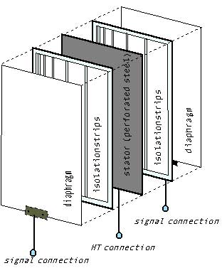
Figure 2, View of the loudspeaker assembly
A central metallic stator (in the prototype an isolated steel sheet 2mm thick, perforated with holes 4mm diameter) forms the heart of the element. At both sides of the stator plastic strips are glued, which divide the element in segments with the same length but with different width. The exact dimensions are shown in fig 3. On the plastic isolation strips at both sides of the stator are glued two diaphragm sheets Before gluing, the Mylar sheets must be tended as well as possible in both directions, to obtain a diaphragm without ripples. The sheet (4 to 12 µm thick) is glued to the isolation pieces with the conducting side outwards (away from the stator). The enclosed air volume between the two diaphragms forms an acoustic coupling, and, contributes in diminishing the second order distortions.
Pieces of conducting material (e.g. print plate) are pressed against the diaphragm's at each side of the element and are connected to the signal leads Fig 2 : View of the loudspeaker assembly Those small plates can be attached to the elements with 2 isolated nylon screws through the sandwich structure. An high voltage isolated wire is directly soldered to the metal sheets (in the middle, underneath the element), and forms the connection to the polarisation voltage To form a real full range ESL, several of this elements can be superposed, hereby extending the frequency range at low frequencies. In this case provisions must be made to interconnect all the elements.
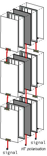
Figure 3, Full range ESL with 3 elements
The bottom- and eventual inner- elements can be wired as described above. The connection of multiple elements is serial : diaphragm with corresponding diaphragm, stator with following stator. Other constructions are possible : stator made of interconnected isolated wires or other conducting materials (I have made ESL's with stators of double sided print board in which I drilled some 10000 holes!). In the last case the copper areas of the print board must be interconnected to get an equipotential surface opposite to each diaphragm. With this kind of construction it is even possible to make a stator consisting of 2 separated, electrically interconnected metal sheets with some space between them, which permits new experiments (e.g. to obtain phase linear sound). In all cases the free area between wires or holes must be 40% to 60% of the total area of the element.
Construction details for the elements
As the first ESL's I build where made with materials I bought in order to reproduce the ESL240 described by E.A.L. Fikier in "HIFI-Luidsprekers 6", the dimensions of the elements and most used construction techniques correspond to those described there. The difference lies in the kind of ESL (with central stator) and in the final result which resides in a much smaller housing.
The Stator
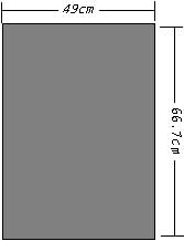
Figure 4
The stator is made of 2 mm thick, perforated steel sheet which contains holes with a diameter of 4mm. Horizontally there is a distance of 6mm between the centers of the holes, and also between the horizontal lines on which the holes lie. The centers of the holes of 2 succeeding lines of holes are shifted 2 mm between each other as shown below :

Figure 5
To eliminate the sharp sides(due to the punching of the holes) the plates where etched (bath of HCL 30%, 48 hours at 20 degrees C). It is also possible to debur the plates mechanically, but the above method is more adequate. Fig 3 : Dimensions of the stator. When the plates are completely clean and free of bursts, 6 layers of painting (alternating white and black acryl painting) are deposed on it. Alternating the colors aids in obtaining an equal deposal of the painting. To finish, 2 layers of polyurethane painting are deposed.
The Isolation Pieces
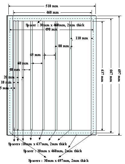
Fig 6 : The isolation strips divide the loudspeaker element in segments with different resonancies, depending on the width of the segment.
The isolation strips, respectively 3cm and 1cm wide, are made out of 2mm thick plastic material. The largest strips surround the element and are glued at each side of the stator, so, that they are half (1,5 cm) on the stator, and half outside. The element is divided in segments of varying width with the 1cm strips, as shown in figure 6.
The Diaphragm
The diaphragm is made of 79 cm wide, 6 µm thick Mylar sheet, covered at one side with Aluminum A piece of film, with a length of 1 m is stretched as well as possible by means of tape on a flat plane, the conducting side underneath. When the film is stretched without ripples, a small layer of glue is deposed on the isolation strips, already attached to the stator, and the assembly stator/isolation strips is deposed on the stretched sheet. Some weight is deposed on the stator (e.g. books) and the whole assembly rests in that position for some 24 hours. This procedure is repeated for the second diaphragm at the other side of the stator.
The Enclosure
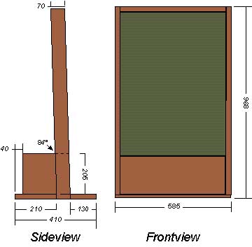
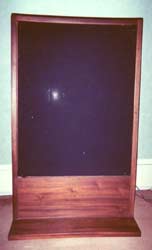
Figure 7, The wooden enclosure
The wooden enclosure is made with the dimensions (in mm) shown in the figure above. The electrostatic panel is lightly inclined backwards (6 degrees ), and is fixed in the middle of the 70mm wide wooden pieces who form the right and left sides of the enclosure. To do so, square wooden pieces (10x10 mm), 67 cm long are glued and screwed to both side panels Some 3mm holes are drilled in the largest (3cm) isolation strips at both sides of the element, as far away as possible from the active area, and the element is fixed through those holes with screws.